Neuropixels Headstage
Introduction
The SpikeGadgets Neuropixels headstage is designed to optimize the power and density of Imec’s Neuropixels probes with the power and modularity of SpikeGadgets’ products. The headstage records neural signals from up to three Neuropixels probes simultaneously, with 2880 selectable neural channels.
The headstage can operate in 2 modes: 1) tethered live streaming mode, where up to 1152 of the available 2880 channels across three probes can be selected and livestreamed to your computer using the Main Control Unit (MCU), or 2) untethered data-logging mode, where up to 400 channels across the three probes can be selected and the data is recorded locally to a microSD card on the headstage.
The Neuropixels headstage can be used with both the SpikeGadgets MCU as well as the Logger Dock, and requires the Trodes application suite, which can be downloaded here. See our Trodes wiki for more information about Installing Trodes.
Please also familiarize yourself with the Neuropixels user manual before recording with this headstage. The manual can be found here.
For additional information about Neuropixels Probes and recording with them, please see the UCL Neuropixels training course here.
- Neuropixels Headstage Specifications
Number of Neuropixels Probes
Up to 3 Standard rodent Neuropixels 1.0 probes
Channel count
Selectable
(up to) 2880
Streamable (via tether)
1152 (across 3 probes) or 384/probe
Wireless data logging
400 (across 3 probes) or 384/probe
Weight (without probes)
Headstage + cone
19.2g
Headstage + cone + 400mAh battery
31g
Record time (with 400mAh battery, 1 probe)
2.5 hours
Power consumption (1 probe)
160mAh
Dimensions
Untethered logging with cone and battery
Length
45mm
Width
25mm
Height
55mm
Tethered streaming with cone
Length
35mm
Width
25mm
Height
45mm
Sampling rate
30 kHz
Bit depth
10-bit
Connection to commutator
micro HDMI
Sensors
Accelerometer, gyro
LED Array
6 LED (3 green, 3 red)
Surgery, Probe Connection & Assembly
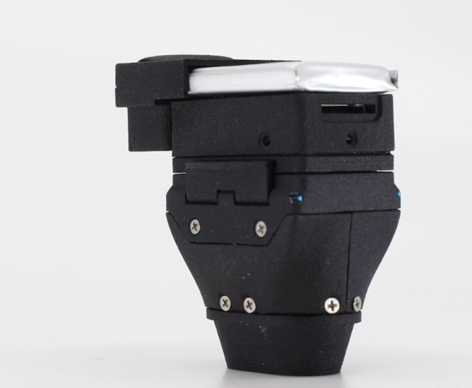
Before beginning the implantation procedure, the cone should be disassembled to reveal the ZIF probe interface connectors. During implantation, the bottom portion of the cone can be further disassembled to make the probe implantation process easier. The cone portion of the Neuropixels headstage must be placed around the implanted Neuropixels probe(s) and attached surrounding the site of implantation. Before reattaching the cone top, the probes are connected to the cone’s headstage interface by inserting the flexible probe connectors into the Zero Insertion Force (ZIF) connectors as shown in the image on the next page.
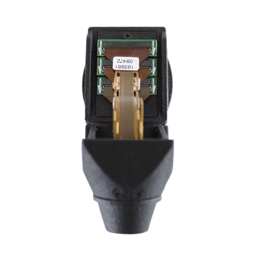
figure 2: Neuropixels Probes connected to cone assembly via tiered zero insertion force (ZIF) connector interface.
Probe, Headstage and MCU Configuration
Probe Configuration
Before a probe can be used it must be programmed with the probe-specific configuration files from Imec that are provided with each probe. This can be done by connecting your headstage to the MCU via HDMI and using the SpikeGadgets probeConfig application (Windows and USB compatible only), which can be downloaded here.
To use the probeConfig application:
Connect the probe to your headstage in the slot you intend to use when recording.
Connect your MCU to your computer via USB, then connect the Neuropixels Headstage via HDMI to your MCU.
Move the probe configuration file from Imec and the probeConfig.exe application to the same directory.
Open the command line and run the probeConfig command line application. When calling the application, the probe slot being configured must be specified (e.g. “probeConfig 1” to configure the probe in slot 1, “probeConfig 2” to configure the probe in slot 2, etc.).
The program will read the probe ID, then look for a probe calibration file that matches the probe ID (in the same directory as the probeConfig application). If found it will apply the configuration data to the probe. If not found it will ask if the probe should be configured using default calibration data instead.
Repeat the process if configuring multiple probes.
If the headstage detects a probe without calibration data, you will see a solid yellow LED signal following the Startup LED blinks on your headstage.
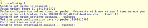
figure 3: Example output from running the probeConfig program to calibrate a probe
LED Indicators
Upon powering on the Neuropixels headstage, the Yellow and Red onboard LEDs will blink in different patterns to provide headstage status indications.
Startup: Probe Detection Following startup, the headstage will blink 3 times to indicate the status of each of the 3 probe slots. Each blink corresponds to a probe slot on the headstage in sequential order (blink 1 = slot 1, blink 2 = slot 2, etc.). Below is a guide to interpreting these LED readouts.
Yellow Blink: Probe detected in slot
Red Blink: No probe detected in slot
Simultaneous Yellow and Red Blink: A probe is detected, but data cannot be acquired from the probe. This often indicates a bad signal connection to the headstage connector or a damaged probe shank.
Example video of probe detection indicating probes in position 1 & 2 here.
Headstage Status Indicators (following startup blinks)
Solid Yellow: Detected probe is not configured (see probe configuration section above)
Solid Red: 1) No probe detected, 2) cannot initialize/sync probe (corresponds with simultaneous R/Y blink above) or 3) probe sync lost while streaming data
Yellow LED Breathing: SD card has been mounted and enabled; ready for recording to start
Red LED Breathing: SD card is full
Fast Yellow Blinking (4Hz): SD card is detected, but cannot be mounted
Slow Red Blinking (2Hz): SD card fails to mount at startup
Fast Red Blinking (4Hz): SD card not enabled for writing
Very Fast Red Blinking (8Hz): Bad data connection detected
4x Yellow Blinks: Data streaming start
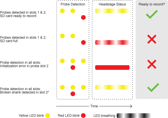
figure 4: Selected examples of headstage LED status indication
*NOTE: If the Neuropixels headstage detects probe shank damage in one slot and an initialization/sync (I/S) error in another slot, the headstage status indication will give preference to the I/S error, displaying a solid red LED indication. This is because I/S errors are often caused by a poor connection to the headstage connector, which can regularly be addressed by reconnecting the probe to the connector. A broken probe shank by contrast can only be addressed by replacing the probe, which is not always practical or possible.
Trodes
Creating a Neuropixels Workspace
From the Trodes main menu, choose “Create/Edit Workspace,” then select “From Scratch.” This will open the Workspace editor.
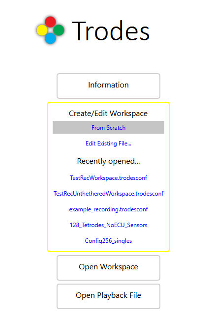
figure 5: Begin workspace creation by selecting “From Scratch” under the “Create/Edit Workspace” dropdown menu
From the Workspace editor, under “Hardware Configuration” select “Headstage: Neuropixels.”
Select the number of probes you are using from the dropdown menu (1,2 or 3).
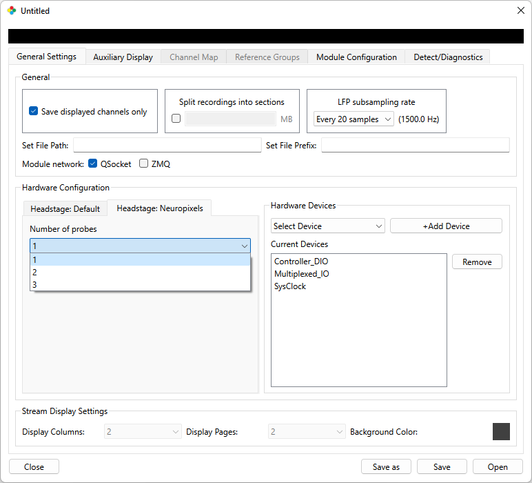
figure 6: Workspace probe selection dropdown menu
If an Environmental Control Unit (ECU) is connected to the system, the ECU device should be added under “Hardware Devices.” To do this, select “ECU” from the “Select Devices” dropdown menu, then click “+Add Device.”
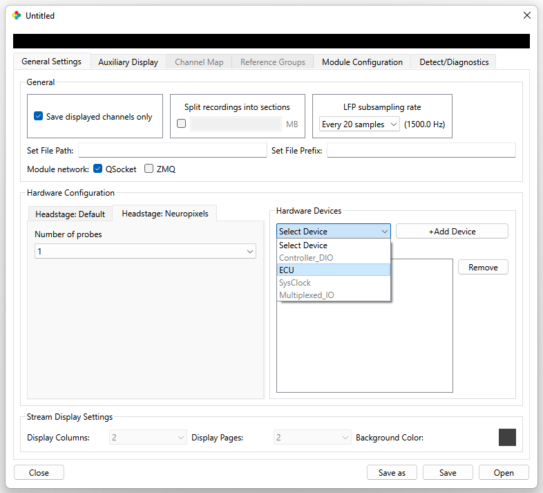
figure 7: Selecting ECU from the Hardware Devices dropdown menu
Click “Open.”
Selection Tool Interface
Each Neuropixels probe is limited to recording 384 distinct channels simultaneously. For tethered live streaming recordings, this means that a maximum of 1152 channels can be recorded simultaneously across 3 probes. For untethered recording, a maximum of 400 channels can be recorded across 3 probes, with a maximum of 384 channels from any one probe. Channels are selected using the Neuropixels interface in the Trodes GUI.
To opens the Neuropixels interface in Trodes, open your Neuropixels Workspace, then select Connection > Specific Source Control > Neuropixels1 from the dropdown menu.
Probe Selection
Choose the probe you would like to format using the “Probe Selection” dropdown menu. Probes will be numbered chronologically, not by slot number. For example, if probes are in slot 2 & 3, the probe in slot 2 will be labeled “Probe 1,” and the probe in slot 3 will be labeled “Probe 2.”
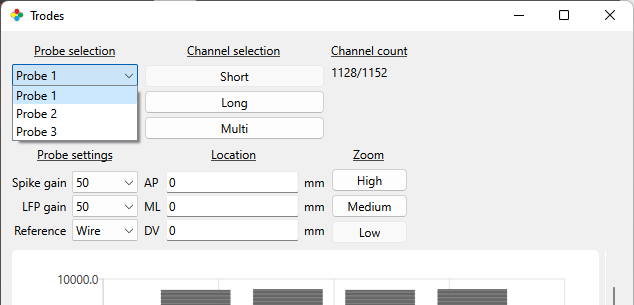
figure 8: Neuropixels interface Probe Selection menu
Channel Selection
The Channel Selection menu allows you to select a total of 384 channels per probe for a total of 1152 channels across 3 probes for tethered recordings, or a total of 400 channels for untethered recordings.
NOTE: The GUI will always list the absolute total channel count for detected probes regardless of recording type (tethered or untethered). For untethered recording, the actual maximum recordable channels remains 400.
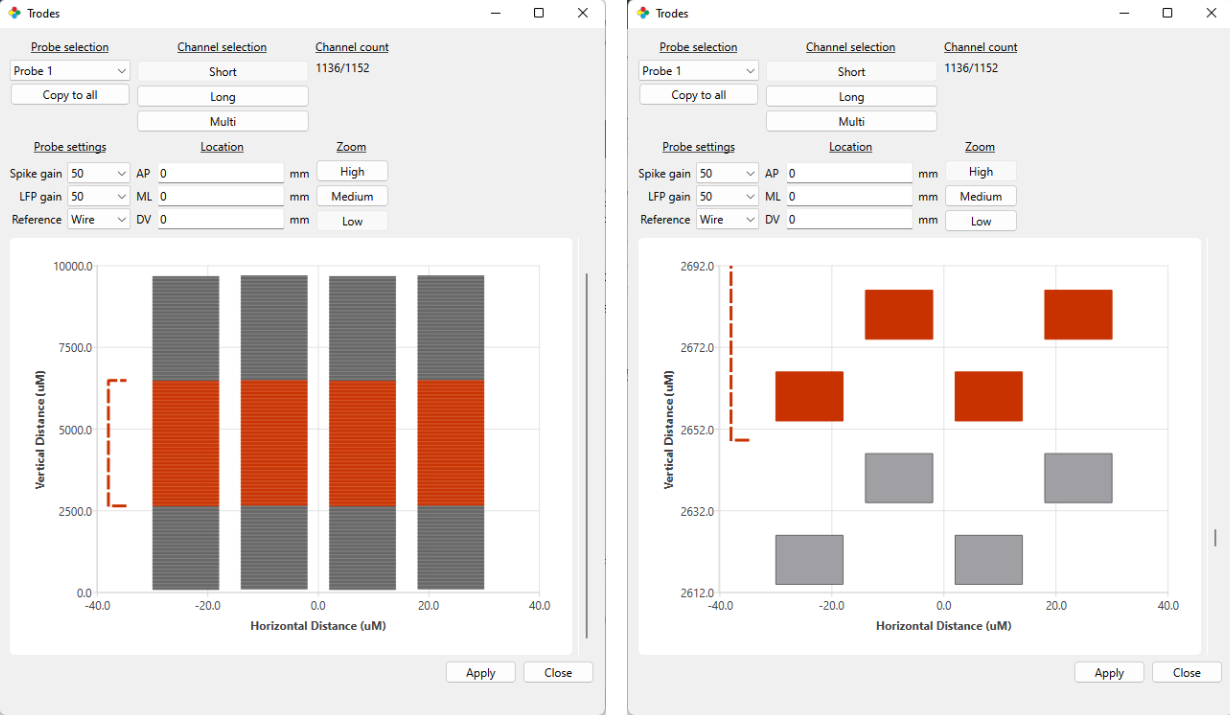
figure 9: Short Channel Selection viewed in low and high zoom
Short - Selects exactly 384 consecutive channels across the probe. The placement of these channels along the probe shank can be adjusted by moving the red dashed range bracket to the left of the channel schematic.
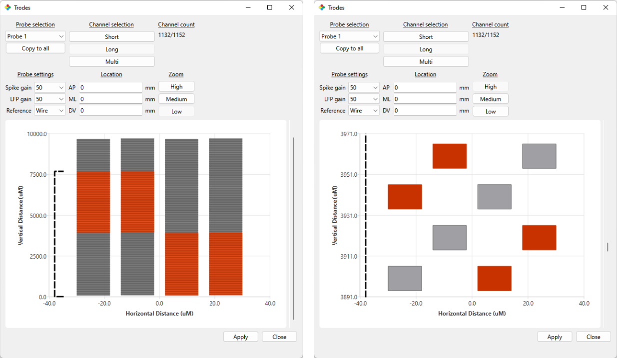
figure 10: Long Channel Selection viewed in low and high zoom
Long - Selects 384 channels in alternating fashion (every other channel is activated). This covers an area twice as large, with half the density of the short selection method. This density is roughly equivalent to that of a tetrode.
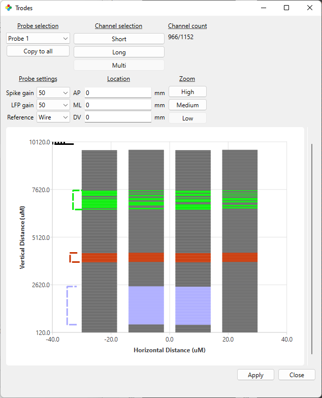
figure 11: Multi Channel Selection showing ranges of varying size with different custom channel selection schemes
Multi - Allows for custom selection of channels. When High zoom is selected in Multi selection mode, individual channels can be turned ON/OFF within a selected range. Custom channel range is selected using the brackets preloaded in the top left of the selection pane. Simply drag one of these brackets to the desired position and set the bracket range by right-clicking the bracket. NOTE: bracket range is expressed in microns.
Multi-channel selection patterns may also be copied to the other probes being used by selecting, “copy to all,” under Probe Selection.
IMPORTANT NOTE: The Neuropixels probe array shank is comprised of 3 channel banks. These banks are connected to a finite number of output nodes, some of which are shared between multiple banks. This means that it is possible to select channels in 2 different banks that output to the same node. While the probe hardware is capable of this output scheme, it results in the voltage signals from both channels being combined. Because this combined channel data can be difficult to parse reliably, Trodes does not allow channels sharing an output node to be selected simultaneously.
This is illustrated in the figure below, where gaps in the red channel range can be seen resulting from the position of the purple ranges selected.
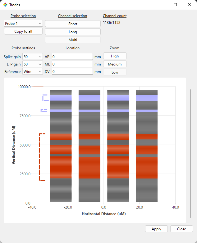
figure 12: Omission of overlapping output channels illustrated by gaps in red channel range resulting from outputs already occupied by purple channel ranges
Probe Settings
Probe Settings is where reference and gain can be adjusted. Neuropixels probes acquire spike and local field potential (LFP) data streams simultaneously but independently. This makes it possible to set a different gain value for each stream. In general, “Gain” refers to how much the signal is amplified before it is digitized.
output signal = GAIN * (input voltage - reference voltage)
Input voltage refers to the voltage at each electrode site. Reference voltage can come from one of three available sites. Neuropixels documentation states:
“The standard recording configuration is to short the external reference with the ground, and connect these to a saline bath (or agar) above the craniotomy for acute implants, or connect them to a skull screw for chronic implants.”
In Trodes this is referred to as the “wire” reference.
NOTE: Unless unique settings are required, it is highly recommended to use the same Probe Settings for reference and gain across all probes for consistency and clarity.
For more information about Neuropixels gain and referencing, see:
https://github.com/cortex-lab/neuropixels/wiki/Gain_settings
https://github.com/cortex-lab/neuropixels/wiki/Referencing-and-Grounding
Zoom
Adjusts channel display zoom. The High zoom setting allows for individual channels to be viewed. When using High zoom AND Multi selection mode (discussed above), individual channels may be selected and de-selected.
Channel Formatting
Channel selections may be color coded by right-clicking any range marker and choosing “set color.” The length of the marker may also be changed in the multi-channel selection format by right-clicking the range marker.
Once the desired channels are selected, click “Apply” to save the configuration to your headstage. This will save the channel selections to the headstage itself for untethered recording or tethered streaming.
Recording With the Neuropixels Headstage
Tethered Configuration and Recording
When recording in tethered mode, the headstage is powered and data is streamed via the HDMI cable connecting the headstage to the Main Control Unit (MCU). When the headstage is properly connected to the MCU, the rightmost LED on the front of the MCU will change from blinking orange to solid green.
NOTE: Any SD card inserted into the headstage must be removed before tethered streaming can be initiated.
On the Neuropixels headstage, the following settings are available for modification under the Settings dropdown menu > Headstage Settings:
Sample Sequence Correction (on/off) The Neuropixels Headstage currently does not support this feature; it is recommended to turn it off
3-axis accelerometer (on/off) - The accelerometer range is +/- 2g, encoded in signed 16-bit integers, sampled at 500Hz. This means each step is 2/32767g or 0.000061g.
3-axis gyroscope (on/off) - The gyro range is +/- 2000 degrees/second at 16 bits, or 0.061deg/sec per step, sampled at 500Hz.
To begin recording:
Open Trodes and your Neuropixels Workspace.
Connect your headstage to the MCU via HDMI, and link your MCU to Trodes using the “Connection” dropdown menu by selecting: Source > SpikeGadgets > USB OR Ethernet
- Configure your probe and channel settings if you have not done so already and hit “Apply” to save the setting to your headstage.
The Neuropixels Probe and channel settings window can be accessed under the Connections dropdown menu by selecting: Specific Source Control > NeuroPixels1
Begin streaming by clicking “Stream from source” under the Connections dropdown menu.
Create a new recording file by selecting “New recording” under the File dropdown menu.
Set your recording directory using the file explorer pop-up window.
Begin recording by hitting the record button.
To end your recording, hit the pause button, and disconnect your stream.
Untethered Configuration and Recording
The Neuropixels headstage can be used in untethered data-logging mode to record neural data directly to an onboard microSD card without the need of a cable tether. It does this under battery power by communicating wirelessly with the MCU or Logger Dock. The MCU or Logger Dock sends start/stop and synchronization commands to the headstage via wireless link.
NOTE: When taking an untethered data-logger recording with your headstage, you must ensure that both the headstage and MCU or Logger Dock are set to the same Radio Frequency (RF) channel and sampling rate, with RF session ID mode turned on.
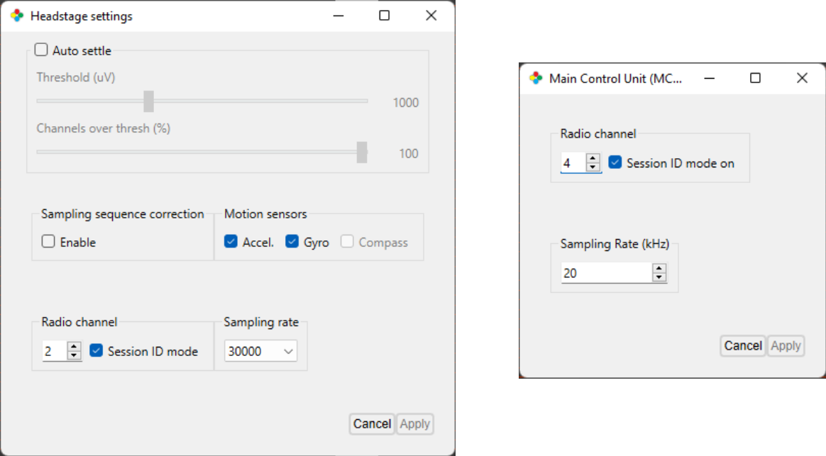
figure 13: Headstage and MCU RF channel, sampling rate and session ID mode
Notice the discrepancy between the headstage and MCU sampling rate and RF channel values in the figure above. These need to be aligned before initiating an untethered recording.
To prepare your headstage for recording:
Open Trodes and your Neuropixels Workspace.
Connect your headstage to the MCU via HDMI, and link your MCU to Trodes using the “Connection” dropdown menu by selecting: Source > SpikeGadgets > USB OR Ethernet
Under the “Settings” dropdown menus, set the MCU and headstage RF channel and sampling rate to the same values and select the session ID mode checkbox for both.
Configure your probe and channel settings if you have not done so already and hit “Apply” to save the setting to your headstage.
The Neuropixels Probe and channel settings window can be accessed under the “Connection” dropdown menu by selecting: Specific Source Control > NeuroPixels1
Save your Neuropixels Workspace. This Workspace can be used later as the basis for the Workspace used to merge your neural and environmental data.
To begin recording:
Disconnect your Neuropixels headstage from the MCU, connect the headstage to battery power, insert your SD card into the headstage and power the headstage on.
For more information about preparing your SD card, see SD Card Setup below.
Open Trodes and create a new Workspace with channel count set to zero. This workspace will be used to acquire the environmental record.
Connect your RF transceiver to the Aux 1 port on the front of the MCU.
Open your workspace, connect to your MCU, and set your RF channel and sampling rate to match the settings you previously applied to your headstage settings, also making sure Session ID mode is checked.
When you are ready to begin recording, select “Stream from source” from the Connections menu. This will trigger the headstage to begin recording.
IMPORTANT NOTE: The headstage will start recording when you begin streaming with the MCU, but the MCU will NOT start recording until you create a new recording file and hit the record button in Trodes. The same holds true to ending your recording; the MCU recording can be ended or paused using the interface buttons, but the headstage recording is ended by disconnecting your stream.
To initiate recording with the MCU, select “New Recording…” from the File dropdown menu and select your recording directory.
Hit the red “record” button to begin recording your environmental record with the MCU.
To end your recording, hit the pause button, and disconnect your stream.
When using the Logger Dock, the Logger Dock RF channel and Session ID mode settings can be set by opening the DataLoggerGUI, selecting the Logger Dock entry that will appear under the “Detected Storage Devices” menu, then clicking the “Edit dock settings” button to the upper right. You will find the RF channel and session ID settings in this pop-up menu.
Batteries and Charging for Untethered Recording
When recording untethered, the Neuropixels Headstage is powered using rechargeable 3.7V Lithium-ion batteries. Attempting to power the headstage using a different battery type is not recommended and can result in damage to the headstage or connected probes. For most applications a capacity of 400 mAh is recommended.
Batteries can be charged using either the SpikeGadgets Battery Charger, or a 3rd party charging device. When charging batteries with any device, it is important that the selected charge rate setting does not exceed the battery specification (e.g. a 400mAh battery should be changed using a 400mAh charge setting or lower). Charging at a rate below the battery spec will result in a longer charge time, but will still fully charge the battery.
SD Card Setup
Before a SD card can be used for untethered recording in data logging mode, it must be enabled. This can be done either using the MCU or the Logger Dock. To do this, place the microSD card into the card reader slot (an adaptor is required when using the MCU).
MCU: Holding down the left button on the front of the MCU while an SD card is inserted will cause the left LED to rapidly flash red, indicating the card is being enabled. The button can be released when the LED turns green.
IMPORTANT NOTE: SD cards should only be inserted into the MCU when being read or enabled, and should be removed following the action. This is because SD cards cannot be read or enabled using the MCU while streaming, and streaming cannot be initiated while an SD card is inserted.
Enabling SD via the Logger dock using the DataLoggerGUI
Once your SD card has been inserted into the Logger Dock, open the DataLoggerGUI application from the Trodes application directory.
Your SD card should be listed under “Detected Storage Devices.” If you do not see your device listed, hit the refresh button.
Hit the “Enable for recording” button to enable your SD card.
NOTE: When using Trodes 2.5.0 or later, the SD card can also be enabled while connected directly to your computer. More information about this can be found here.
Synchronization
Synchronization between the environmental record recorded by Trodes on your local computer and the neural data recorded to SD on the headstage is done via a radio signal sent at regular intervals (10-second intervals for most setups). This signal is transmitted from the SpikeGadgets hardware that acquires your environmental data and connects to your computer. Trodes connects to this hardware to display and save the environmental data during the recording session. Any video recordings taken using the Camera Module in Trodes are set up the same way they would be for tethered recording.
Importantly, the neural data being recorded to SD cannot be accessed during recording. Once the recording session is done, there will be 2 data files that need to be merged. One data file contains the neural data and is saved to the headstage SD card, the other contains the environmental data saved to your computer. These two files will be aligned using the synchronization signals saved to both files, and will be merged using the DataLoggerGUI.
Transferring and Merging Data
In order to merge your data files into a single .rec file you will need the following:
The file containing the recorded neural data from the headstage SD card.
The file containing the environmental data recorded to your local computer by Trodes.
A Trodes workspace file to append to the merged file.
NOTE: This is NOT the workspace file used to record the environmental data, but rather a workspace that contains both environmental record settings as well as probe and channel setting as if the recording were taken in tethered mode. If desired, the saved Neuropixels workspace created above can be adapted for this purpose.
More information about merging your data files can be found in the data extraction subsection of the DataLoggerGUI documentation.