Stimulation
Introduction
The SpikeGadgets Stimulation system is low-latency solution for electrical stimulation experiments requiring current stimulation for up to 256 channels across 8 headstages while recording neural data. The Stimulation system provides sub-millisecond stimulation response times with a high degree of channel count flexibility. The Stimulation system has been optimized for headfixed experiments, but can also be used for some freely-moving experiments with lower channel count.
About the Hardware
The SpikeGadgets Stimulation system is comprised of the Stim-Capable Headstage Combiner Unit (SHCU) and the 32-channel Stimulation Headstage (UH32Stim). The SHCU and UH32Stim work together and are controlled by the SpikeGadgets Main Control Unit (MCU). The SHCU connects directly to the MCU via HDMI and supports up to 8 simultaneously connected Stimulation headstages (256 channels). The SHCU and connected Stimulation headstage(s) are recognized by the MCU and Trodes as a single headstage with flexible channel count. As such, the following are true:
The channel count detected by the MCU and Trodes is determined by how many Stimulation headstages are connected to the SHCU.
Channel ID is continuously numbered 1-256 across the 8 HDMI headstage inputs. This means that HDMI input 1 records channel IDs 1-32, HDMI input 2 records channels 33-64, and so on to channel ID 256.
sHCU HDMI inputs cannot be skipped. If using only 1 headstage, it must be connected in input 1.
Ethernet connection from the MCU to computer is required when using the Stimulation system.
Stimulation is delivered by the UH32stim headstage using Intan RHS2116 Digital Electrophysiology Stimulator/Amplifier Chips, which receive stimulation commands from Trodes via the MCU and SHCU. The headstage samples at 30KHz, and each channel can be independently switched to stimulation mode to source or sink programmatically defined current updated at the sampling frequency.
Each UH32stim headstage is equipped with 2 16-channel RHS2116 stimulation/amplification chips, which amplify, digitize and multiplex analog signals, and are capable of delivering electrical current on any channel. The chips can source and sink currents ranging from 10nA to 2.55mA enabling precise biphasic stimulation, and are equipped with fast amplifier artifact recovery circuitry for fast switching between stimulation and recording modes. The RHS2116 delivers precise current stimulation by measuring the impedance of the electrode medium (generally the brain) at the stimulation site. The measured impedance is then used to determine the voltage required to produce the desired current.
Testing Considerations:
1. When testing the stimulation system outside the brain, it is important to remember that the headstage needs a valid impedance measurement in order to produce a stimulation. This means that current must be able to pass between the cathode and anode (through some medium). Most often this means connecting the headstage to a test board where all channels are connected to ground, or connecting the headstage to an electrode array submerged in a conductive medium such as saline. Electrode contacts or headstage pins in open air will return an invalid (infinite) impedance value, which cannot be used to produce stimulation.
2. Raw voltage values recorded under artificial test conditions such as those described above will differ from those recorded from the implanted probe and should only be used as confirmation that a stimulation occurred.
Charge Balancing
When stimulating in the brain it Deep-brain stimulation combined with simultaneous recording presents multiple challenges. Problems that may arise include tissue damage, electrode degradation, and stimulation artifacts on recording channels. To curtail these potential problems, one of the most important factors to consider is how electric charge is balanced on the stimulation electrodes when the pulses are presented.
For most applications, it is critical that the total amount of charge sourcing and sinking is balanced between the anode and cathode. Any unbalanced charge can create dangerous tissue heating, damage to electrodes, and for experiments with simultaneous stimulation and recording, any residual charge will cause spikes in the recorded voltage that persists long after the pulse. If the anode and cathode are selected to be on different electrodes in the recording array, you must make sure they are nearby each other. Distant anode/cathode pairs will not allow adequate charge balancing and may result in tissue damage or electrode degradation. If you are using different pulse amplitudes for the anode and cathode, the pulse widths that balance total charge must be used.
In rare cases, it may be preferable to deliver a monopolar stimulation or stimulation that is intentionally unbalanced (electrolytic lesions, etc.). By default, the stimulation script blocks this from occurring. Under circumstances where an unbalanced stimulation is desirable, the optional override_charge_balance input argument can be used. To do this, change the default value from “true” to “false.”
Trodes Installation and Hardware Setup
Download and install Trodes. The latest version of Trodes can be found here. Information about installing Trodes and setting up the USB and Ethernet connections to your MCU can be found here.
Set up trodesnetwork.
Connect the sHCU to power and plug it into the MCU via the HDMI neural data input port on the back of the unit. The MCU must be connected via Ethernet to the local computer.
Connect up to 8 32-channel Stim headstages to the sHCU.
Turn on your MCU. The power LED should turn solid green. If the LED remains flashing orange, this means the Stim system is not recognized; power cycling the MCU and sHCU may resolve the issue.
Once you have confirmed that you Stimulation system is recognized by the MCU, stimulation can be tested using the stimtest Python script packaged with the Trodes application. This script can be found in the following location inside the Trodes install directory:
Resources > PythonExampleScripts > Stimulation
Stimulation Configuration
Stimulation waveform and pulse train parameters are sent to the sHCU via Trodesnetwork, where they are stored in hardware for the session. The commands will be parsed on the control hardware (MCU) and translated into an event queue of low-level commands going to the stim/record chips. The sHCU translates the command into a buffered array of low-level commands going to the headstage(s) stim/record chip. Once triggered, these buffered low-level commands will be sent to the chips at the sampling rate of the headstage (30 kHz) until the entire pulse train is completed or a stop command is given. In between pulses in the train, the target channel(s) will switch back to recording mode.
These settings are configured and stimulation is initiated by the user using Python. The stimtest example script mentioned above can be used to send basic stimulation commands to a single stimulation channel or pair. More complex stimulation protocols can be created by adapting the stimtest script.
Stimulations can range from 10nA to 2.55mA. Any given range is divided into 256 current steps. The current step size is defined by the current scaling value selected. Stimulation amplitude is set by selecting a current scaling value and step number (0 to 255). The following current scaling values are available: 10nA, 20nA, 50nA, 100nA, 200nA, 500nA, 1uA, 2uA, 5uA, and 10uA.
A few examples:
To set stimulation amplitude to 10nA: current scaling = 10nA, pulse amplitude = 1
To set stimulation amplitude to 1uA: current scaling = 10nA, pulse amplitude = 100, OR current scaling = 20nA, pulse amplitude = 50, OR current scaling = 100nA, pulse amplitude = 10, etc.
To set stimulation amplitude to 2.55mA: current scaling = 10uA, pulse amplitude = 255
The script uses 10 main parameters to define the characteristics of a biphasic stimulation train using 1 or 2 channels (the anode and cathode channels, which can be the same channel for monopolar stimulation).
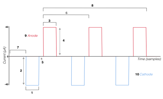
Leading pulse width (samples)
Leading pulse amplitude - 256-step resolution divided across the current scaling amplitude range
Second pulse width - the charge balancing pulse width does not need to be the same length as the Leading pulse, but the amplitude and duration must be charge balanced with the Leading pulse (unless the override_charge_balance argument has been set to “true”).
Second pulse amplitude - must match the leading pulse amplitude
Interphase dwell (samples)
Pulse period (samples)
Start Delay (samples)
Number of pulses in train
Anode channel
Cathode channel (can be the same as the anode channel for monopolar stimulation)
IMPORTANT NOTICE: In versions of this script released prior to Trodes 2.6.0, the stimulation amplitudes exported to Trodes was calculated incorrectly. These reported values were lower than the actual stimulation values. Specifically, these values were reported assuming a fractional relationship between pulse amplitude and step sizes (10nA, 20nA, 50nA, 100nA, etc.) rather than the actual multiplicative relationship. For instance, if current scaling = 10uA and pulse amplitude = 255, this will result in a 2.55mA stimulation. Previously, this would have been reported as 10uA.
Stimulation Triggering
Using Python, each pulse train is added to a user-defined “slot” and “group.” Each train must be assigned to a unique slot, but a group can be assigned one or multiple train definitions. A stimulation is initiated by triggering the slot (one train) or group (one train, or multiple trains triggered simultaneously).
NOTE: Slot triggering a single stimulation train does not work in some versions of Trodes. This is noted in the stimtest script. Assigning only one train definition to a triggered group provides the same function.
Trodes Workspaces
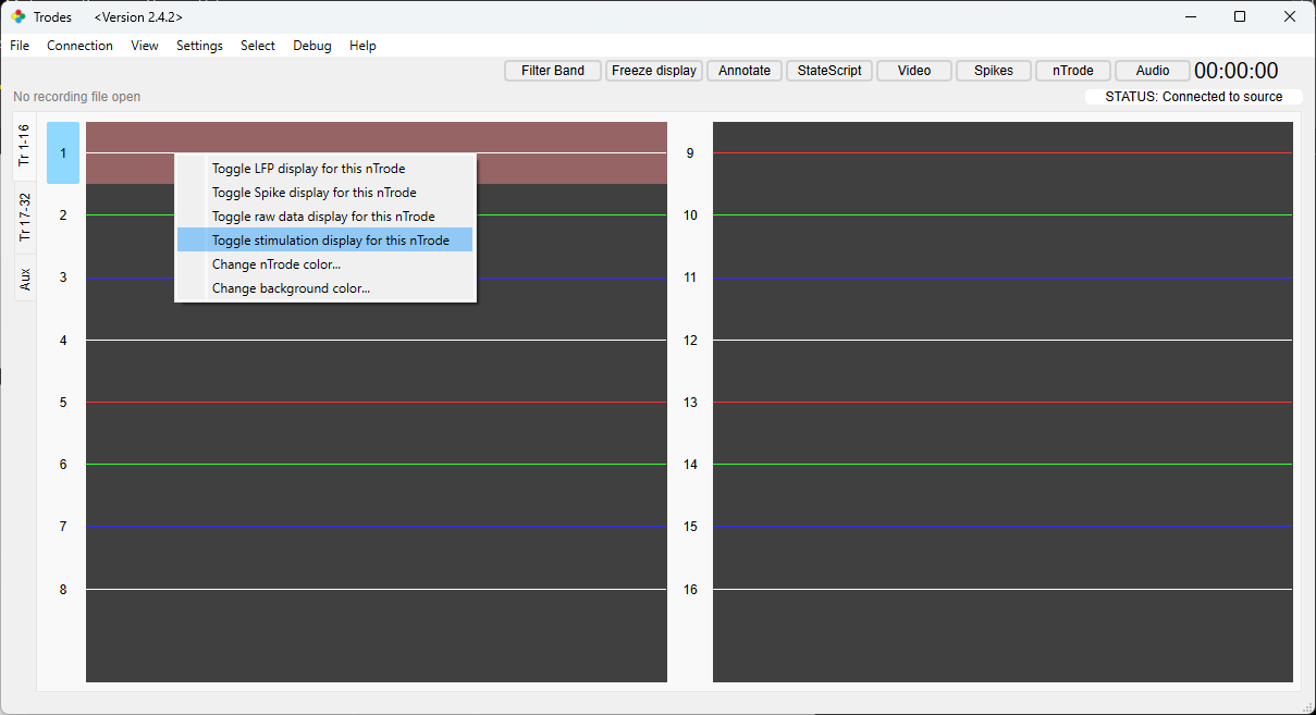
When creating a Trodes Workspace for stimulation, the channels being used for stimulation must be togged on for stimulation. This is done on the Channel Map settings tab during workspace creation by changing the value in the “Stim Capable” column from zero to one. This makes it possible for stimulation triggers to be viewed in Trodes while recording. To view the stimulation trigger signal on any given channel, right-click the channel and select “Toggle stimulation display for this nTrode” as shown below. Neural data cannot be viewed on this channel while stimulation mode is displayed, but the data is still recorded.
For general workspace creation guidelines, please visit the Workspaces wiki page.
Trigger Stimulation
The Stimulation system used Trodesnetwork to control stimulation via a Python script. This is done by running the Python Script containing the stimulation protocol and configuration settings while connected to the MCU and Stimulation system. The stimtest script packaged with Trodes (mentioned above) can be adapted for this purpose, or a new script can be written to meet your needs. The Python script can either be triggered manually by the user, or using StateScript.
Additional Documentation
For more information about the Intan Technologies RHS2116 use to amplify, digitize and stimulate, please see the datasheet.